
- #Uno r3 schematic how to
- #Uno r3 schematic serial
- #Uno r3 schematic software
- #Uno r3 schematic code
- #Uno r3 schematic download
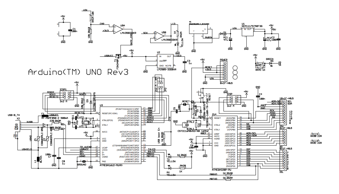
Well chop it up after and analyze every section according to their function. Why would you want/need to modify the board? Dont worry if you cant see it much right now. altiumdesigner pcbdesign pcblayout pcb3d arduinopcb( )COMPARTE Y SUSCRIBETE Arduino UNO R3 Schematic & PCB Layout Altium Designer Arduino UNO R3. Ok so is there ever a scenario where I would want to use the other resistors on the USB input or can I just leave that alone? The number at the end of each is the PIN number in the pack. Note the resistance is 22ohms on all resistors. These are two resistors in the pack that are used. Look at the USB input and you will see 2 x 22 ohm resistors RN3A and RN3D. These are 2 resistors in a resistor pack that are on the board but not connected.

Why would i want USB ground to be connected to main ground? According the to schematic, it looks like they need to be separate, but don't have to be.įinally it makes sense why the reset bridge is in there!

The pads make it easier to restore the cut. I read somewhere that it may be desired to cut the RESET trace under some circumstances. The GND allows the USB GND to be connected to the main GND. The solder bridges make it easy to join the circuit if required. Check this link if you want to try it out as well.Thanks for the great response, it's all starting to make sense! I have just a few questions about what you said. Also, I did a tad for the season of gift giving. I did a test on an TFT LCD previously, you might want to check it out here. Get updates on technical articles like this by staying tuned on Learn. If you have comments or suggestions, feel free to write below. This is an article for the basic arduino schematic diagram after all. Quite refreshing to see the board again right? By now, you should be able to appreciate how these are connected to the several electronic components in our schematic diagram. We can also see here the two lines where the two microcontrollers communicate. When the ATmega 16U2 transmits or receives a signal from the ATmega 328P, yellow LEDs light up. They are used for ESD (Electrostatic Discharges) protection. On the other hand, Z1 and Z2 are varistors. It slows the speed of the USB pulses lessening EMI interference. They are used so that the total impedance of the line matches with the USB specification. These RN3 resistors are termination resistors. This MCU has capacitors, an ICSP header and a crystal as well. This is basically the same with the main microcontroller section. Since the main microcontroller, ATmega328, does not have a USB transceiver, we use the ATmega16U2 microcontroller as a bridge to translate the USB signals from your computer to UART, the communication protocol the ATmega328 uses. Looking at the schematic, the 16U2 TX/RX lines go to the TX/RX lines on the 328P and the Uno header.
#Uno r3 schematic software
I have a need to test some PC software with an FTDI232 interface, instead of the 16U2 USB chip on the Uno R3. We don’t use this way of programming often since we can already do it via USB, which we will discuss in the next section. I have an Uno R3 that works just fine with the built-in USB interface. Usually, we only use this for remote programming or for flashing of the microcontroller for the first time.

#Uno r3 schematic serial
The ICSP (In-Circuit Serial Programming) Header is used to program the ATmega328P using an external programmer ( e.g. We’ll chop it up after and analyze every section according to their function. Don’t worry if you can’t see it much right now. Here we have the schematic diagram of the latest revision of Arduino UNO.
#Uno r3 schematic how to
Nearly all of them explains how to make it work but, how does it work? A good understanding of the hardware design will help you learn how to incorporate them on your machines, small-scale to large. There are a lot of tutorials for Arduino in the internet. Two and the more popular use of the term is that the board itself is called an Arduino. This is the also the reason why we can only do a diagram analysis of Arduino, and not a Raspberry Pi. The only downside of giving the public access is that it gives birth to competition.
#Uno r3 schematic code
With the code and design free, public collaboration can develop the product way faster than any proprietary product. Open-source means its source code and hardware design is freely available for anyone to modify.
#Uno r3 schematic download
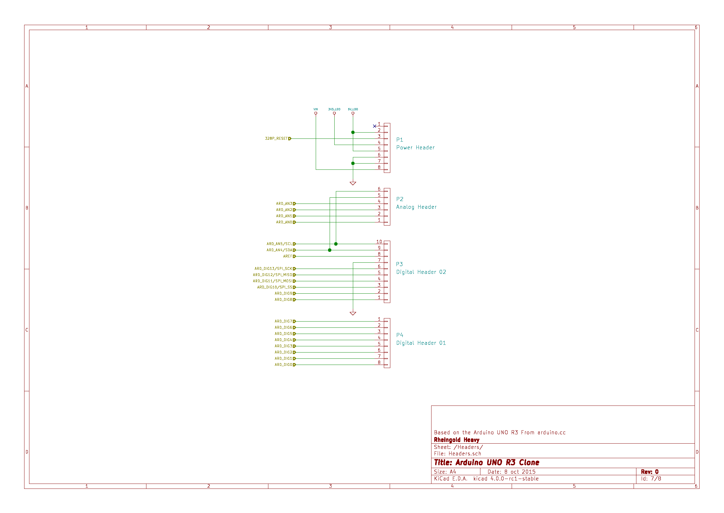
I advise you to download it and open the PCB and schematic using Eagle CAD while you are reading this article. One, it is an open-source hardware and software company that creates circuit boards that makes microcontrollers easier to use. I redistributed the original Arduino UNO schematic to be more readable below.


 0 kommentar(er)
